The form of gear teeth for the Analytical Engine
To build an authentic version of the Analytical Engine we need to understand the form of the teeth which Babbage used on his gear wheels. While it will undoubtedly be the case that modern tools and methods will be used …
以下正文同步自 Hacker News 最新,版权归原站所有,已转换为易读排版。
To build an authentic version of the Analytical Engine we need to understand the form of the teeth which Babbage used on his gear wheels. While it will undoubtedly be the case that modern tools and methods will be used to actually fabricate parts, we should nevertheless aim to reproduce the original intent as closely as possible, rather than blindly substituting parts made directly to modern standards. Unfortunately, Babbage seems to have written nothing on this subject, so all we have to work from are the drawings. Despite being exquisitely executed in most cases, it is still not possible to determine precisely, from the drawings alone, the detailed geometries of gear teeth at the level necessary for manufacturing, so we need to search for other clues to inform our decisions. Indeed, most of the drawings do not show the gear teeth in detail at all, just the basic pitch circles for the gears, sometimes with additional circles to indicate the tips and roots of the teeth. Where teeth are drawn, it is often only in the elevation view, and while this allows the depth of the teeth to be determined with adequate precision, it tells us nothing about the actual tooth profile. In the few cases where teeth are shown in plan view, they may have been drawn using a simple template for drafting convenience, and not meant to be definitive for manufacturing purposes. A common practice at the time was to draw radial flanks and simple circular arcs, centered at the intersection of the pitch circle and the flank, for the faces. This appears to have been the case on most of the drawings. Babbage had been working with the same draughtsman, Jarvis, since the original Difference Engine No. 1 in the 1820s when it was certainly the case that wheelwork was a craft of the skilled artisan, so he probably just carried on with the same drafting techniques he had used back then, without regard for any recent progress in the gear art. Much might still have been left to the skill, knowledge, and experience of the craftsmen who would have been called upon to actually fabricate the wheels.
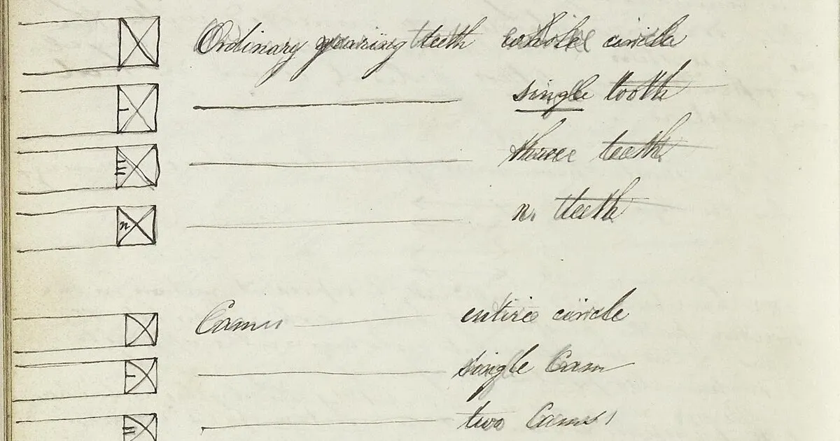
Babbage adopted a standardized notation on the drawings to distinguish various forms and functions of teeth (though without defining their detailed forms). He identified three classes: regular gear teeth, used to pass motion from one wheel to another as in standard gearing; locking teeth, used in conjunction with a locking lever of some form to precisely define the position of wheels when not in motion; and cams, special teeth formed or mutilated in particular ways to act on other parts in specific ways which vary on a case by case basis. He documented this in the Sketchbook.1 Teeth are marked in elevation using a cross with lines drawn diagonally between opposite corners. A straight cross indicates a regular gear tooth, a cross formed from concave lines with the crossing point towards the center of the wheel indicates a locking tooth, and a cross formed from convex lines with the crossing point away from the centre of the wheel indicates a cam. Figure 1, taken from the Sketchbook entry, illustrates this. Babbage provided an additional indicator for the number of teeth in the case that less than the full circle are to be provided, but he rarely, if ever, used this additional indicator on the actual drawings. He further states that, in the case of locking teeth and cams, the corresponding parts with which these interact should be similarly marked.
Here, we are only concerned with the regular gear teeth. Locking teeth, usually triangular in form, present no issues. Details of cams or teeth mutilated for special purposes (intermittent or interrupted motion, cam action of some form) must be deduced from the drawings together with an understanding of the specific motions intended to be produced when they act.
We should first consider the state of the art when Babbage commenced work on the Analytical Engine. The theory of gear tooth forms had been worked out by French and Swiss mathematicians in the previous century, particularly by Camus around 1733, Euler around 1745, and de la Hire, who as early as 1694 had recommended the use of the involute curve for gearing. However, that theory had not been put into practice in English workshops, where gear making was more a craft and an art. Dudley states: ‘The skilled craftsman could make gears that would fit and run smoothly without having even heard of an involute or a cycloid.’2 Babbage however, was well versed in continental mathematics, and so might have been familiar with the theoretical work of Euler.
Things began to change with the introduction of cast iron gears in millwork to replace earlier gears which had used wooden cogs fitted into a wood or iron frame. Wood can flex and absorb the shock loads created by imperfections in the teeth. But cast iron could not, and imperfections resulted in noise, excessive wear, and with prolonged use, fatigue failure. The important consideration in the design of gear teeth to eliminate these problems (aside from the obvious requirement of adequate accuracy in their production) is that they should communicate uniform motion. That is, if the driving wheel turns uniformly, so should the driven wheel.
The Englishman Robert Willis, professor of natural and experimental philosophy at Cambridge University, was a pioneer in gear engineering. He wrote and taught extensively on the gear art, and in 1841 published the influential book: Principles of Mechanism, Designed for the Use of Students in the Universities, and for Engineering Students Generally. This book contains a lengthy chapter devoted to the forms of gear teeth which would deliver the required uniform motion, principally the cycloidal and involute forms, and Willis advocated for the involute form.3 Interestingly, it also contains a chapter titled “On Mechanical Notation” wherein he quotes at length, and sometimes verbatim, from Babbage's 1826 paper on the subject.4 Curiously, despite his work being substantially quoted here, and his stated desire that the Mechanical Notation should be taught in universities and engineering schools, Babbage does not appear to have owned a copy of this book, though surely he must have been aware of it.5
In 1835, the pre-eminent English machine toolmaker Joseph Whitworth was awarded a patent for the first gear cutting machine tool using the hobbing principle.6 This process uses a rotating cutter, in conjunction with a synchronized rotating blank, to generate a full set of perfectly formed teeth in a single continuous operation. For the cycloidal tooth form, a large number of distinct cutters would have been needed, because this tooth form depends not only on the number of teeth in the gear to be cut, but also on the number of teeth in the gear it is intended to mate with. In contrast, for the involute tooth form, a single cutter for a particular pitch of gear can be used to create wheels of any number of teeth. What is more, the form of this cutter is particularly simple as it requires only straight sided cutting teeth. This was a revolutionary step forward, because up to this point teeth had to be cut individually using form cutters made to match the space between teeth, which space itself varies with the number of teeth on the wheel to be cut. Unfortunately, limitations in creating the cutter at the time meant that Whitworth's machine could only cut spiral gears, not the straight toothed spur gears that the Analytical Engine requires. That limitation was only overcome much later in the century when in 1889 George Grant, an American pioneer of gear manufacturing, was awarded a patent for a machine using this method.7 Writing the following year, Grant noted when speaking of the Whitworth machine: ‘It was invented in 1835, and has not been materially improved since then, although there are numerous patents relating to it.’8 The London Science Museum holds one of the original Whitworth machines, dated to around 1854, in almost pristine condition, with a broad set of change wheels, as seen in Figure 2. By definition, change wheels, which needed to be selected according to the required relative motion of the hob and the gear blank, needed to be interchangeable, and so we presume Whitworth would have made them using the involute, rather than cycloidal tooth form. Modern mass produced gears are generally produced in the involute form by a hobbing process.
Whitworth had worked for Joseph Clement on Babbage's original Difference Engine and Babbage was in correspondence with Whitworth through most of his life. In a letter to a ‘Rev. Pearson’ in 1869 he said:
I have heard at different times from men I have employed in former years that amongst their own class it was said that:
Mr. Babbage made Clement
Clement made Whitworth
Whitworth made the tools.9
When later in life he was contemplating building a version of his Analytical Engine in the 1850s, Babbage ordered some machine tools from Whitworth.10 Thus it is reasonable to assume he kept abreast of Whitworth's latest developments and we might therefore expect he would have used Whitworth's state of the art machine tools had he been seriously interested in building the Engine of Plan 27.
However, despite the advantages of the involute tooth form, industrial practice continued to use almost exclusively the cycloidal form until late in the century, and that using mostly form cutters on machines of increasing sophistication and automation.11 So we conclude, despite Whitworth's invention, Babbage would most likely have adopted the cycloidal tooth form had the engine been built in the 1840s.
Let us return now to the problem at hand, defining the precise form of the teeth for the gears of Plan 27. We should be up front in saying that, at least in the data-path of the Analytical Engine, the gears only ever move slowly and are not called upon to transmit significant power. In effect, the wheels are being used to count teeth, not transmit power. Further, as the machine is inherently digital in nature, using the extensive system of locks to ensure correct alignment at the end of any motion, the exact nature of the teeth is probably of little practical importance. Any tooth form which meshes freely, even if it does not deliver the uniform motion so important in power transmission applications, will probably work satisfactorily. Indeed, the author's own Meccano models of some of Babbage's machines and mechanisms used gear teeth formed from nothing more than bolt heads and yet calculated correctly. Nevertheless, with our eye on authenticity, let us consider the issues in more detail, keeping open for now the choice between involute and cycloidal tooth forms.
In most of the drawings up to and including those of Plan 27, the gears are characterized by short, stubby teeth, with wide flat tips. However, the wheels of the subsequent Plan 28, which interestingly are drawn in much more detail and showing most of the teeth, have very long and fully pointed teeth. We might wonder why the sudden change—had Babbage stumbled on some new insight into gear design? No, what changed here was that, in order to reduce height, Babbage eliminated the dedicated triangular locking teeth, and applied the locking lever directly to the regular gear teeth instead. With the older, short stubby teeth, applying locks to those teeth would have significantly reduced the amount of correction a lock could provide, because any large error in the position of the wheel would result in the lock colliding with the flat top of the tooth and jamming. However, the fully pointed teeth of Plan 28 allow the lock to provide the same degree of correction (fully half a tooth) as previously achieved with the dedicated triangular locking teeth. There is in fact one place where Babbage had already used this technique in Plan 27, for the outer teeth of the long stepping pinions. After the change to the reduced unit of space following Plan 13, there was no longer roo
正文由 探How 从来源站点 RSS 同步,内容未经改写;遇到排版缺失或需要图片、视频时请以原文为准。