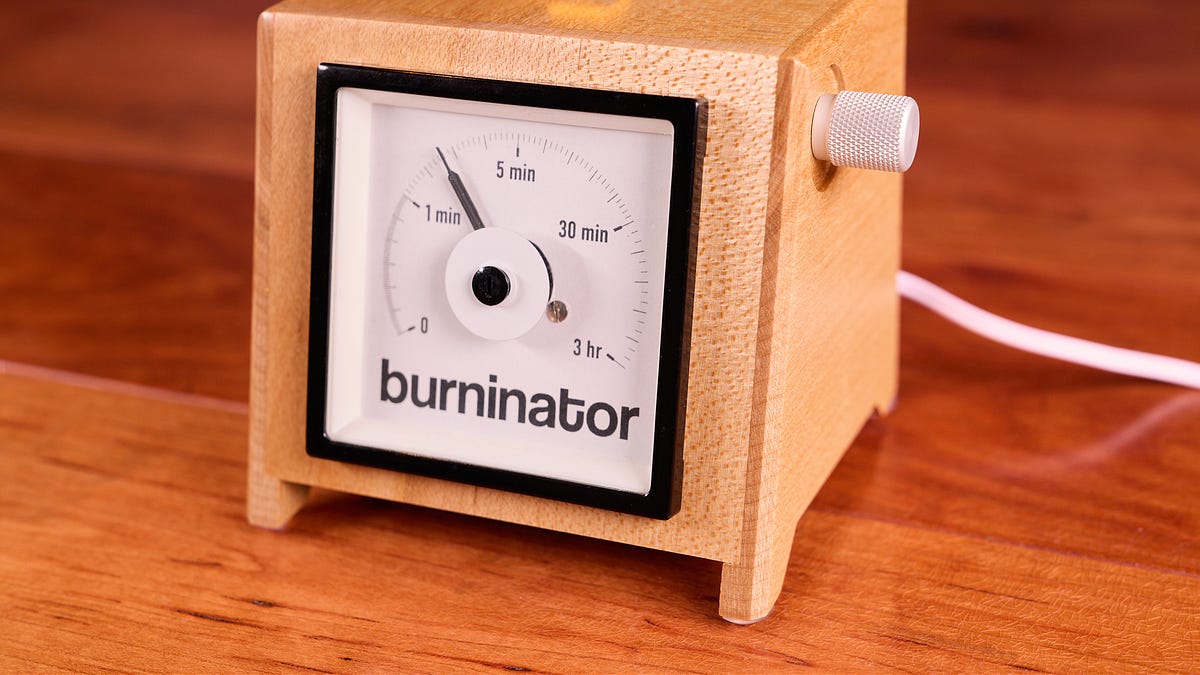
Quasi-Logarithmic Kitchen Timer
Like some of you, we have several kitchen appliances with integrated digital timers. I find them annoying: they are clunky to operate and if one uses them while cooking, the reflective surface gets covered in muck.
以下正文同步自 Hacker News 最新,版权归原站所有,已转换为易读排版。
Share
Like some of you, we have several kitchen appliances with integrated digital timers. I find them annoying: they are clunky to operate and if one uses them while cooking, the reflective surface gets covered in muck.
Confusing, alien, evil technology.
You can buy mechanical (wind-up) kitchen timers, but they’re imprecise and only ring once. There’s also a couple of cheap battery-operated units that can be adjusted by twisting an outer ring, but they have so-so reviews.
But if there’s no good product to buy, why not make your own? I decided to build a digital timer with an old-school analog display and an easy-to-use adjustment knob. Further, to improve precision and legibility, I figured it would be nice to go with a logarithmic scale.
Well, sort of: a truly logarithmic display wouldn’t work well with customary time units. That said, I came up with a compromise solution that divides the dial into four linear sections:
Dial design (printable PDF version here).
In the section up to the one-minute mark, major ticks represent ten-second increments. The next section covers 1 to 5 minutes, major ticks every minute and minor ticks every ten seconds. The third section spans 5 to 30 minutes, with five-minute major ticks and one-minute minor ticks. Finally, for the range from 30 minutes to 3 hours, every major tick is half an hour and every minor tick is ten minutes.
Although this sounds complicated, the scheme is self-documenting: the labels “1 min”, “5 min”, and “30 min” describe both the corresponding timer setting and the stepover in the section that follows. For example, three minutes is just “1 min” plus two major ticks, while 20 minutes is “5 min” plus three ticks. It doesn’t take long to get a hang of it.
For the actual electromechanical display, I repurposed a vintage, switchboard-style Crompton 244-05VG-LS panel meter. Internally, the device is an ammeter with a full scale of 1 mA. Analog meters of this sort have gone out of fashion but they’re still available from surplus outlets; I scored this pair on eBay for $30 each:
Switchboard-style meters, after modification (left) and before (right).
To make a custom face for the meter, I simply disassembled the device, measured the dimensions, and printed replacement graphics on adhesive paper.
With the display sorted out, I sketched out the design of an enclosure. I kept it uncomplicated to make the unit easy to clean:
A rough CAD sketch of the enclosure.
To make the enclosure, I grabbed standard 4/4 maple stock and resawed it on a bandsaw. The assembled enclosure is shown in the photo below:
Let’s cook.
Most of the effort was getting the UI right. The timer is activated by tapping an illuminated button on top and then dialing in the desired time with a knurled knob mounted on the side. The wake-up tap is meant to eliminate nuisance activations. The active period is 20 seconds, indicated by a beep and a steady LED. If there is no encoder input in that time window, the device goes back to sleep.
The countdown starts three seconds after the last encoder input, provided that the chosen interval is greater than zero. While the timer is running, the interval can be seamlessly adjusted with the knob. Once the countdown reaches zero, the device enters an alarm mode and stays making noise until the button is pressed again. The alarm can be also canceled by turning the knob clockwise to add more time.
Similarly to my earlier voltmeter clock project, the circuit uses an 8-bit AVR DB series microcontroller ($1.50) and drives the meter using single-bit PWM with a variable duty cycle on pin PC0:
Circuit schematic.
Square-wave audio is produced by a small speaker driven via pin PA6. An inexpensive 250 mA rail-to-rail op-amp, AD8531 ($1), is configured as a voltage follower to amplify the signal; many other chips with a reasonable current capacity — say, OPA310 ($0.80) — should also work fine.
The speaker I used is probably CUI CMS-3048-058SP ($2.50). The encoder is Bourns PEC16-2220F-N0024; it produces 24 pulses per revolution and has detents that provide a nice tactile feel. The whole circuit is powered by a compact 5 V wall wart, CUI SWI5-5-NW-P5.
The code running on the MCU can be found here. For a demo, check out the following clip:
Of course, all of this is very outmoded. The modern approach to hobby projects is to have an LLM do everything, then slap your name on it and submit straight to Hacker News. Alas, I come from a token-poor household, so I needed to do this by hand.
正文由 探How 从来源站点 RSS 同步,内容未经改写;遇到排版缺失或需要图片、视频时请以原文为准。