Show HN: I built ESP32-S3 LED tubes for live coding
This project documents my personal experience building a 3D-printed LED tube, controllable over WiFi.
以下正文同步自 Hacker News 最新,版权归原站所有,已转换为易读排版。
This project documents my personal experience building a 3D-printed LED tube, controllable over WiFi.
It was born out of a personal need: I wanted lights for my live coding performances, and as a software developer with a 3D printer I had fun building a system that lets me control lights from the browser with minimal latency at a reasonable cost.
The firmware and the 3D models are designed around the hardware I used. Take them as a starting point and adapt them to your own setup.
The current build is a 1-meter tube with a 24V FCOB strip, driven by an ESP32-S3 microcontroller, all powered by a 24V supply and controllable over WebSocket or UDP. You can build as many strips as you want — just connect them to the same network.
browser → WebSocket → CLI proxy (ws) → UDP → ESP32-S3 → RMT peripheral → LED strip
Browsers cannot send UDP directly, so the CLI exposes a local WebSocket proxy that bridges to the device. The ESP32 receives the UDP packets and updates the strip through the RMT peripheral, which generates the signal in hardware without involving the CPU.
The first time, the device is configured over USB from the site or the CLI, or over BLE with the CLI. After rebooting, it joins the network and is ready to receive commands.
I started developing the firmware out of curiosity and to have full control over the realtime path. Only later did I take a closer look at WLED, which supports UDP control through DDP.
In tests with ESP32-S3 boards and 16 segments, WLED and reactive-leds were equally smooth at 60 fps. With 90 and 120 fps streams, stock WLED coalesced updates and rendered about 62 frames per second, while the included firmware rendered every frame without drops. For normal browser use at 60 fps, this difference is not significant.
WLED is not currently supported. If you would like to use it with reactive-leds, open a GitHub issue or submit a pull request.
This is a small monorepo. Each main area has its own folder and its own README.
Build/flash the firmware: see firmware/README.md.
CLI tools for testing: see cli/README.md.
Using the JavaScript client: see client/README.md.
Protocol/types: see shared/README.md.
Materials
24V FCOB LED strip
XL4015 DC-DC module (24V → 5V)
ESP32-S3
24V power supply
Power cable
JST (alternative) pick the 3-pin variant (VCC, GND, DATA)
330 Ω resistor in series on the LED data line
These are the materials I used, but the project adapts to similar strips and components. Just make sure to configure the firmware for your strip (color order, number of segments, etc.). ESP32-S3 modules with PSRAM are fine, but PSRAM is not required for this use case: the realtime LED path uses small buffers in internal RAM.
If I were to improve the build, I would replace the somewhat fragile JST connectors and add a way to support the solder joint at the start of the LED strip.
The models and settings are only a starting point — I am not a 3D printing expert. The enclosure is designed to house the ESP32-S3 and the DC-DC module listed above, together with a 12mm LED strip rail.
For the rail I printed five 20 cm PLA pieces: either five profile pieces, or four profile pieces plus the optional profile_head. For the diffuser I used four 25 cm pieces of transparent PETG.
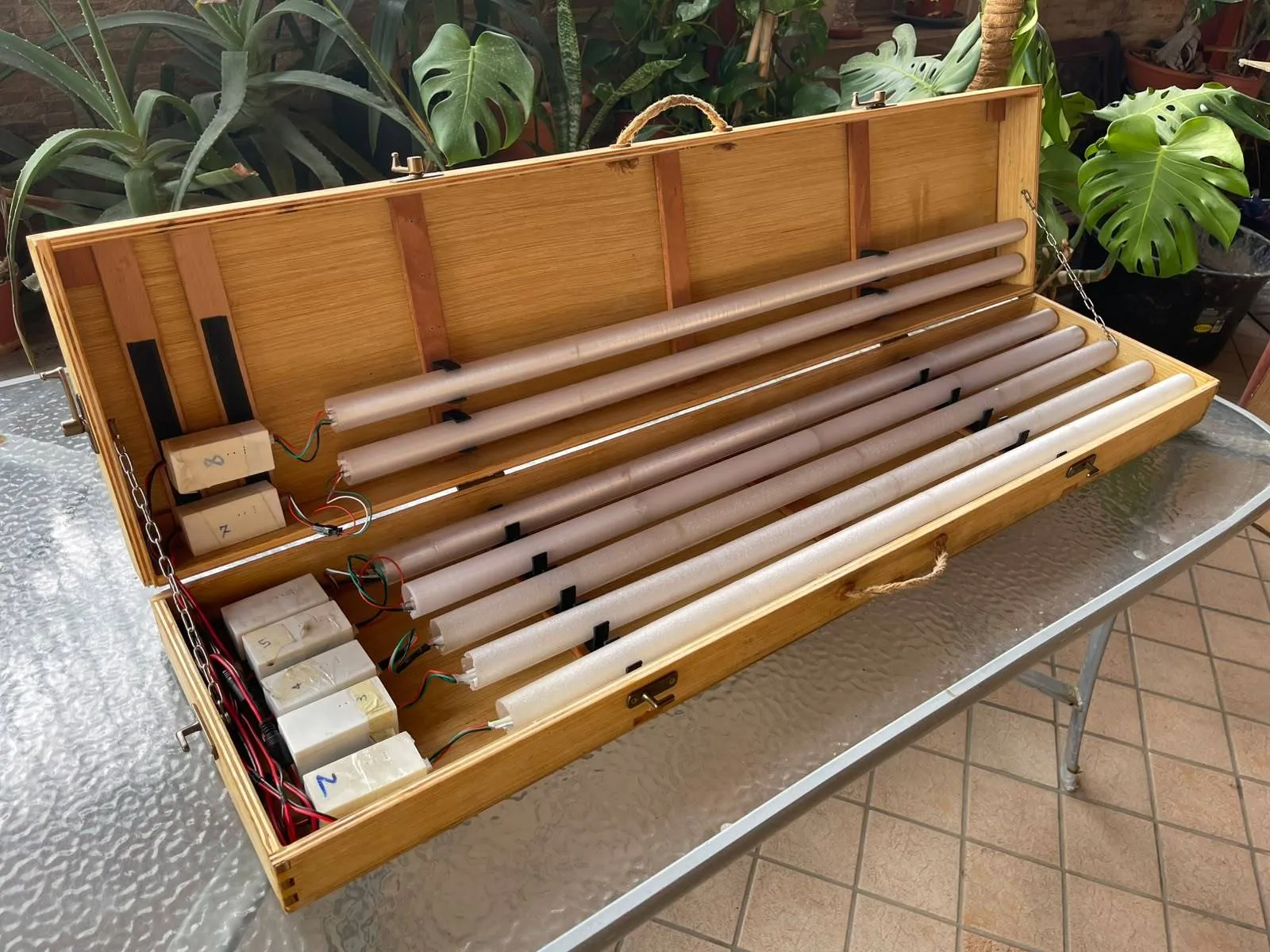
At first I carried them in a cloth wrap with elastic bands, like a roll-up pencil case, but I did not feel they were secure enough. I later built a wooden case based on this tutorial and printed PLA parts to hold the LED tubes inside it. The case fits 12 tubes.
Segment-level control, not per-LED: the FCOB strip has 896 LEDs per meter but only 16 ICs per meter. Control happens per segment (16 segments/m), not per individual LED. This is a deliberate choice: I preferred a brighter strip over resolution.
255 LEDs per device: num_leds and start_index are single bytes in the UDP protocol. More than enough for segment strips (~15 m of FCOB per device); it is not designed for high-density matrix panels.
Color order: the RGB/WRGB byte sequence depends on the strip's IC. The firmware is configured for the strip listed in Materials. Different strips may need a different order (see firmware/main/leds.c).
WiFi sleep disabled: the WiFi radio power-saving mode is explicitly disabled to avoid latency spikes and packet loss during real-time updates.
WiFi credentials in cleartext over BLE: during provisioning the credentials are sent unencrypted. For a personal project simplicity wins, but keep it in mind on sensitive networks.
Power and safety
The LED strip runs at 24V. Power supply sizing depends on the strip's specs and the real load — as a reference, with all LEDs on the strip draws roughly 1 A per meter. Use a supply with adequate headroom and proper wiring.
The firmware and CLI are licensed under GPL-3.0-only. The client and shared packages are licensed under MIT; see the LICENSE file in each directory for the full terms.
正文由 探How 从来源站点 RSS 同步,内容未经改写;遇到排版缺失或需要图片、视频时请以原文为准。