Build a Hidden Lock with a Magnetic Imager
Like many a nerd, I have a certain fascination with locks. This originates in reading the memoir Surely You’re Joking, Mr. Feynman as a teenager, in which Richard Feynman recounts picking locks and cracking combinations…
以下正文同步自 Hacker News 最新,版权归原站所有,已转换为易读排版。
Like many a nerd, I have a certain fascination with locks. This originates in reading the memoir Surely You’re Joking, Mr. Feynman as a teenager, in which Richard Feynman recounts picking locks and cracking combinations while at his day job working on the Manhattan Project at Los Alamos. I currently have a couple of locksport pick sets and training locks that I purchased at hacker conferences over the years (although I’m still terrible at it), and I delight in the YouTube exploits of folks like the LockPickingLawyer.
All of which left me wondering if I could try building an interesting lock. One dodge that lockmakers have long used to challenge would-be plunderers is to conceal the existence of the lock itself. A modern variant of this is the magnetic lock, where a magnet is held or slid against an innocuous portion of a door or box, releasing a catch. The problem with this is that, once you guess the location of the lock, any strong magnet will open it.
So I started thinking about embedding an RFID reader under the surface and resigning myself to keeping track of yet another access card. But then I stumbled across something much more interesting: SparkFun’s US $100 magnetic imaging tile. I realized I could use this to build a magnetic lock that opens with a programmable secret gesture.
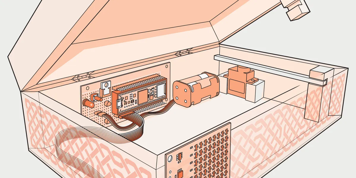
I used a few discrete components to drive the servo motor and put the lock into program mode [top], controlled by a Teensy 4.1 microcontroller [middle]. An array of Hall-effect sensors detect magnetic fields [bottom].James Provost
The magnetic imaging tile is a small-run SparkFun board based on the work of Peter Jansen. It features an 8-by-8 grid of Hall-effect sensors, and uses an SPI interface to talk to the microcontroller of your choice. These sensors can detect both the magnitude and polarity of a magnetic field, and the board can report its measurements hundreds to thousands of times per second, depending on how much processing power your microcontroller has available. This is easily fast enough to capture the motion of a magnet being moved by hand across the board’s sensor area—my secret gesture.
An interesting thing about using magnetic fields is that if I was in extreme paranoia mode, I could shield the entire lock behind copper sheeting, something I couldn’t do with an RFID reader. The copper sheet would act as a Faraday cage, blocking any RFID signal, along with any other electromagnetic fields an attacker with an EMF meter might use to locate the lock.
I chose a Teensy 4.1 as my microcontroller. I like the Teensy because it offers loads of input/output, a 600-megahertz processor, a megabyte of RAM, and a built-in SD card, all in a slim package with an equally slim $32 price tag.
Wiring the Teensy to the magnetic-imaging tile was trivial, only complicated by the fact that one side of the board has a silk-screen error that misidentifies the SPI connections (SparkFun says this will be fixed in future runs of the board).
In extreme paranoia mode, I could shield the entire lock behind copper sheeting.
To create the gesture-recognition software, I once again turned to vibe coding. If you read my Hands On piece in the April 2026 issue of IEEE Spectrum on creating a teletext suite for ham radio, you’ll know I’ve been grappling with how vibe coding should be used in DIY projects, if at all. So this time, instead of letting Claude write all the software, I confined it to writing just two support libraries, which you can find in our online repository at https://github.com/IEEESpectrumHandsOn.
One library is in charge of recording a lock gesture and saving it to the Teensy’s nonvolatile storage. The other library monitors the tile and reports whether or not a newly detected gesture passes a selectable threshold to be considered a match.
I wrote the top-level code myself to keep it as DIY as possible. This code handles things like a button that puts the system in gesture-recording mode after a brief delay, the indicator LED for recording mode, and the code that operates the physical locking mechanism.
Hall-effect sensors rely on a current passing through a p-type slab of silicon. A magnetic field passing through the silicon deflects charge carriers toward the edges of the slab, creating a voltage proportional to the field [left]. By looking at the intensities of the voltages across an 8-by-8 grid of sensors, the microcontroller can reconstruct a gesture [right]. James Provost
Of course, I needed something to lock to demonstrate my proof of concept. I bought a wooden craft box and removed the existing lid latch. I glued a notched beam inside the lid and built a mechanism that uses a servo motor to rotate another beam in and out of this notch. I will be the first to admit this mechanism goes beyond “simple” and into “simplistic,” but it’s sufficiently robust for my demo. The box has ample room for the magnetic imaging tile to be mounted against one wall, along with the Teensy and other supporting electronics. These include a battery pack, the recording button, and a small additional board with two NPN transistors. These convert the Teensy’s 3.3-volt control signals to a 5-V signal needed to drive the servo.
Once it was all put together, I soon discovered that the small size of the magnetic tile’s sensing area—just 3 centimeters square—made it easy to fit the tile inside the box but hard to do the unlock gesture on the outside so that it is read correctly. Marking the outline of the sensor area on the outside defeated the point of having a hidden lock, so instead I once again turned to mining my Irish heritage. I created a Celtic knotwork pattern that runs in a band across the front of the lockbox (I used an online knotwork generator and then projected and traced the pattern onto the box). Using the pattern as a camouflaged reference grid I can make a repeatable gesture within the confines of the sensor area. (To make the gestures I’m using a magnetic stylus borrowed from a ferrite core-memory kit we featured in 2022.)
There’s obvious room for improvement in any more serious installation. The biggest drawback currently is that if the box is locked when the battery runs out, you can’t open it again without breaking something. This could be solved by adding a hidden inductive charging coil. Nonetheless, the demo lockbox works well—now I just have to think what I should store in it!
正文由 探How 从来源站点 RSS 同步,内容未经改写;遇到排版缺失或需要图片、视频时请以原文为准。